Advance XR Hardware Study
Feb 2016 - Jan 2024
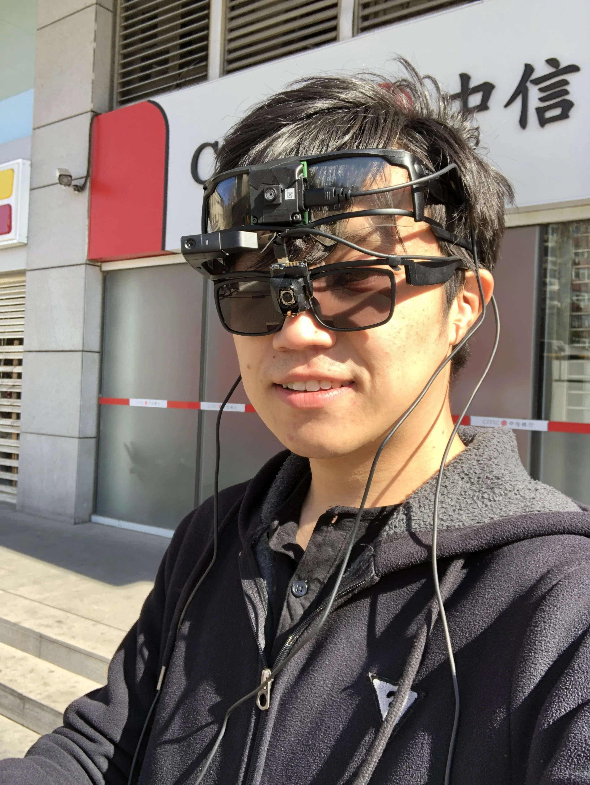
Over the past 8 years of leading and participating in XR hardware design and development, I've been closely following the evolution of key XR technologies. During this time, I've had the opportunity to interact with hundreds of suppliers and evaluate a significant portion of their technology solutions. This extensive exposure has given me a comprehensive understanding of the hardware technologies that can significantly impact the user experience of XR products.
Contributions
Technology Research, Supply Chain Development and Management
Display
Display is one of the core technologies in XR. It can be divided into several components: image source, optical lenses, light engine, darken filter, and prescription lenses. Continuously refining the first three components is crucial for creating an ideal XR visual experience. In this discussion, I will delve into several XR-related technical solutions.
Firstly, regarding display methods, both Optical-See Through (OST) and Video-See Through (VST) can deliver a narrative-fused visual experience. However, current OST displays suffer from issues such as inaccurate color reproduction (especially difficulty in displaying deep colors and blacks), limited field of view (FOV), significant distortion of the real world seen through the lenses, flare, and the inability to provide hard-edge occlusion. These limitations hinder their ability to deliver a satisfactory XR experience, particularly for consumer markets. Nevertheless, in certain niche areas, especially enterprise markets, OST, with its physically semi-transparent display medium, avoids the latency issues associated with VST video streams and does not pose safety hazards in case of power failure. Therefore, there is still a sizable potential market for OST. In contrast, VST is poised to dominate the XR market in the next decade due to its superior narrative-fused experience.
My previous work primarily focused on augmented reality using Optical-See Through (OST) technology. I'd like to further discuss the differences between various OST technologies:
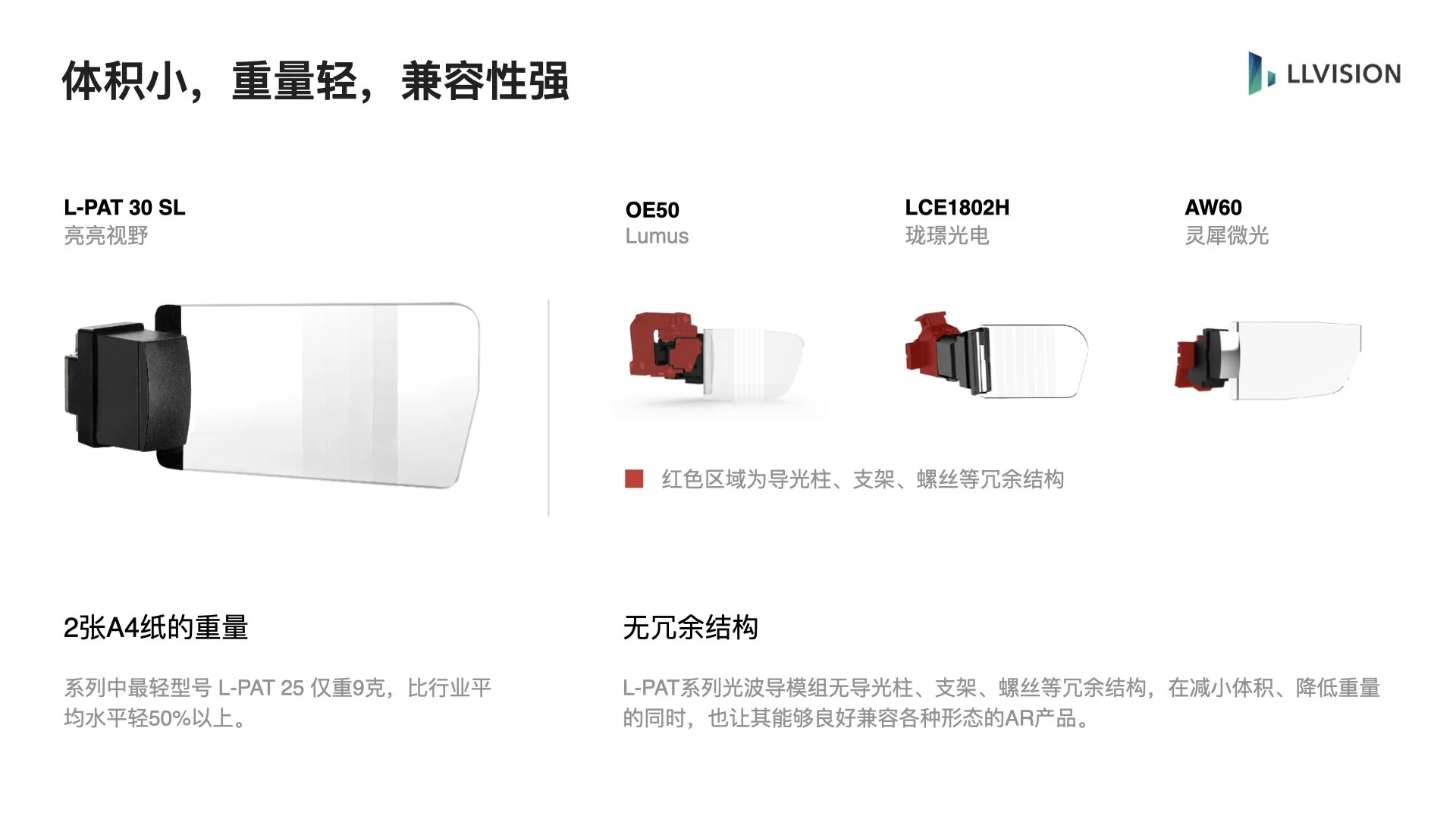
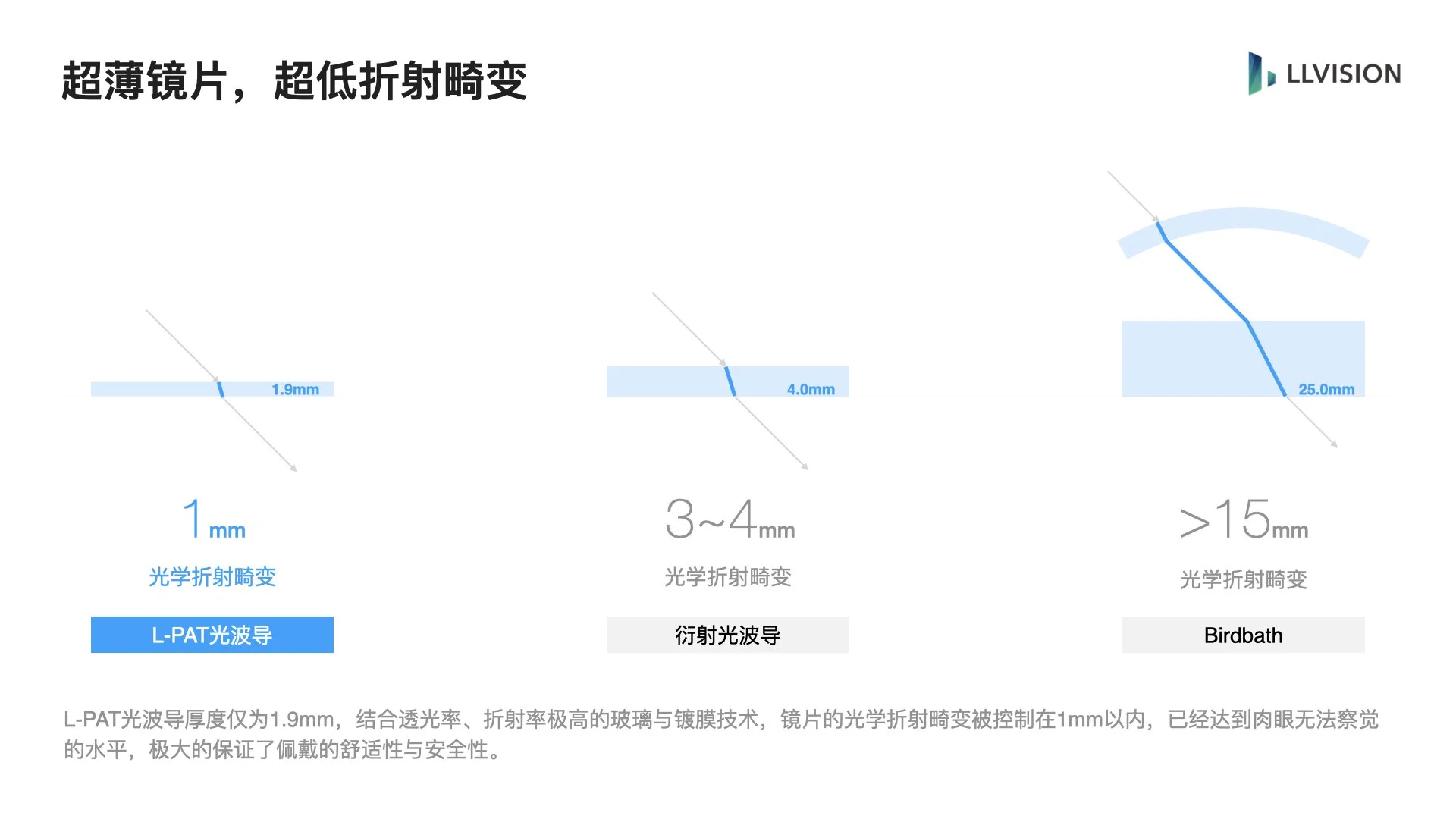
Diffractive waveguide: Each of the R, G, and B color channels requires a separate lens, resulting in a thicker, heavier lens and increased light deflection. Additionally, the overall optical efficiency is relatively low, increasing the power consumption of the light engine. Other issues include poor brightness uniformity, significant color errors, severe diffraction rainbow stripes, and high demands on the supply chain's lithography process. However, the optical engine design is more user-friendly, and lightweight AR glasses can be produced using monochromatic OST displays in the short term. In the long run, this is the optical technology solution that is currently closest to the ultimate OST AR.
Array waveguide: Advantages include thin lenses, high light transmittance, and the ability to be designed and manufactured based on traditional geometric optics. It also offers high optical efficiency, which is beneficial for low-power platforms. However, the light engine of this solution has a rather prominent appearance, significantly impacting the product's aesthetics. While reducing the size of the light engine by converting the waveguide area into a two-dimensional pupil expansion, it loses its volume and weight advantages compared to other optical solutions. Overall, this is considered a transitional technology in recent years.
Free-form: It can achieve a relatively large field of view (FOV) with a reasonable size, weight, and power consumption, and can also integrate the refractive power adjustment function of prescription lenses. However, after miniaturization, its basic thickness cannot be compressed, affecting the product's appearance and the degree of light deflection. It still has technical value in specific application scenarios for a long time.
Bird-bath: Similar to free-form, it can achieve a large FOV and integrate the refractive power adjustment function of prescription lenses with a good size and weight. However, the low optical efficiency leads to higher overall power consumption and extremely low light transmittance. Due to its significant advantages, it is currently the most suitable optical technology solution for consumer OST AR in the next few years.
Photopolymer: It can achieve a very thin lens design, but the light projected onto it has a hazy appearance and low clarity. It was one of the early lightweight AR glasses technology solutions.
Beyond the lenses, the image source within the light engine is also crucial. We believe the mainstream image sources have the following advantages and disadvantages:
OLED: Offers accurate color reproduction, low power consumption, small size, and no backlight. Micro-OLED, in particular, is closest to the ultimate technical solution for XR displays. However, most devices of this type currently suffer from low brightness across the full spectrum, short lifespan, and low production yield.
LCoS: Offers high brightness and mature manufacturing processes but requires a backlight. It is currently only suitable for special products and applications and is considered an outdated technology overall.
Laser + MEMS: Can achieve high brightness and a wide field of view in a very small form factor. However, MEMS can only provide high-resolution display in one direction, and the laser image source must be below Class 0 for safe use. It is currently in the exploratory stage.
Given the need for outdoor use in strong light, we have also introduced photochromic and electrochromic technologies to create the outer lenses of our OST XR devices. The former has poor controllability and a slow color-changing speed, and has been phased out. The latter has been favored by enterprise users - users can enjoy the high transmittance and real-world viewing experience of OST while simultaneously adjusting the dimming level according to the current scene. However, since electrochromic technology cannot modify the imaging distance, even with pixel-level color control, it still cannot achieve the hard-edge occlusion that is essential for ideal OST XR.
To achieve an ideal XR display, we also need a higher angular resolution exceeding 57 PPD (Pixels Per Degree), an image source with lower pixel persistence, and a display and rendering effect that is indistinguishable from reality. However, these goals will require many more years of continuous iteration.
Electronic components
Given the extremely demanding low-latency requirements of XR products, it's insufficient to rely solely on algorithms to reduce latency. Based on my research, I've summarized the following points:
IMU: As the component with the highest sampling rate on XR devices and the only one that has the potential to reduce device latency to the millisecond level through warp algorithms, we must ensure that its sampling rate is ≥ 1000Hz under any conditions. This requires the IMU's default sampling rate to be 1500-2000Hz or even higher, and it must not drift under high-temperature conditions caused by device heating.
Camera: Effective calibration of dual cameras must be based on a precise relative positional relationship. Therefore, the cameras must be mounted on structural components with high precision and that are not prone to errors caused by thermal expansion and contraction. Similar to the IMU, it should not exhibit significant drift or increased noise after heating.
PCB and FPC: To ensure signal transmission quality, we need to use low DK/DF circuit boards to reduce errors.
Materials
Advances in materials science have significantly improved the wearing comfort, reliability, and development process of XR devices. In the past 5 years, chemical companies such as Arkema and DuPont have introduced a variety of new resin materials suitable for wearable devices, including Pebax® and Zytel®. Four types of products specifically designed for XR device housings are worth noting:
Ultralight: These materials have a density of less than 1g/cm³. While other properties may be average, they are suitable for the non-functional cosmetic surfaces of XR devices.
High Strength: These resin materials reinforced with carbon fiber or glass fiber can provide a modulus of 14-18GPa while maintaining a density below 1g/cm³. They can often be used as a substitute for metal components in XR hardware, achieving sufficient rigidity with a lower weight and reducing costs through injection molding.
High Temperature Resistant: These materials exhibit excellent high-temperature resistance, thermal conductivity, and self-thermal radiation efficiency, making them suitable for the housing parts of XR devices that provide heat conduction and passive heat dissipation.
Antibacterial: Filled with antibacterial materials, these are suitable for parts of XR devices that come into contact with the skin.
New nanomaterials can also significantly reduce the size and weight of XR devices in terms of thermal insulation and heat dissipation. For example:
Aerogel: By applying an aerogel sheet less than 1mm thick to the inner side of the device's skin-contacting housing, heat-carrying air molecules will find it difficult to quickly pass through this insulation layer with pores less than 70μm, slowing down the rate at which the device reaches thermal equilibrium.
Graphene: The heat from electronic components can be rapidly transferred through a graphene film less than 0.1mm thick. Even in smaller cross-sectional areas of XR devices (such as the temple area), this material can still provide good thermal conductivity, ultimately allowing for the full utilization of the hardware's maximum external surface area for heat dissipation and preventing heat accumulation, thereby improving wearing comfort.
Additionally, we have experimented with foam gaskets from Sekisui. This material not only fills gaps in the device to prevent stray light from entering the light engine and causing glare on the OST XR device lens but also provides excellent drop protection.
3D Printing
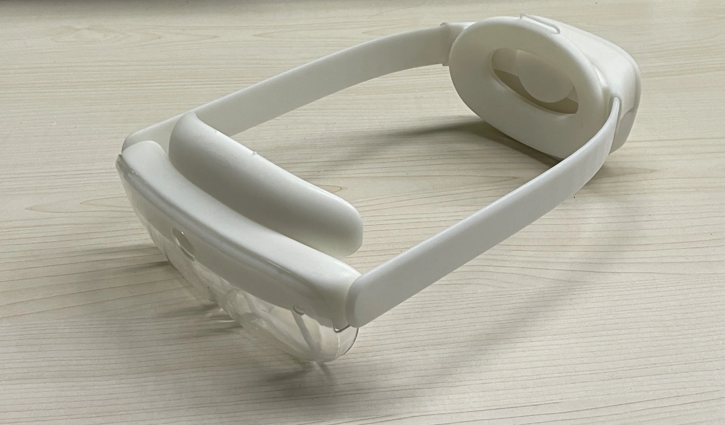
In the past, 3D printing technology struggled to produce high-performance finished products, limiting the use of 3D printed XR device components to appearance demonstrations and evaluations. However, we've discovered a different approach with recent advancements in 3D printing technology:
High-precision printing: EnvisionTec's E-RigidForm not only achieves a bending and tensile modulus exceeding 2500 MPa but also provides a printing accuracy of up to 0.1 mm, making it possible to construct precise near-eye display positioning structures. With this technology, we have produced numerous prototypes with excellent display accuracy for market and user research, something that was unimaginable in the past.
High-strength material printing: Markforged's samples left a deep impression on us - a printed sample only 2 mm thick could not be bent by hand, a level of strength we had never seen before in 3D printed samples. Based on this solution, we have produced many environmental protection samples that would have otherwise required the completion of final engineering prototypes, and tested them under harsh conditions. This has significantly reduced the time required for late-stage structural design and supply chain production in our projects.


